Hydrostatic tests for Oriented PVC pipes: procedure and recommendations
TOM® PVC-O pipelines of a pressure network are part of an integral system that interact with the rest of the elements and equipment that form it.
To guarantee an optimum performance of the networks in which TOM® pipes and other connecting elements are used, it is not only necessary to adapt these networks to the particulars of geotechnical behaviour, and to verify that the design and placement of the needed safety elements meet the requirements of the installation, but it is also essential to ensure the integrity of the pipes and of the rest of the elements by subjecting them to water pressure tests, before putting them into service.
To perform the pressure tests with the maximum guarantees it is advisable to follow the Standard UNE-EN 805:2000 (“Water supply – Requirements for systems and components outside buildings”) recommendations. Nevertheless, it is important to bear in mind that the instructions given by the Project Manager and the General Technical Specifications document will prevail over any other indication.
Among the recommendations to consider we can highlight:
- It is recommended that pressure tests are carried out within the first 8 weeks of installation.
- Pressure tests should be carried out by stretches with the length established according to the UNE-EN 805:2000 specifications either in the project or by the project manager.
- The obligatory execution of a general test of the distribution network through motor pump units of the pump station, should not exempt from the partial achievement of tests carried out on the different sections of the network.
- Pipes of different materials, diameters or nominal stiffnesses should not be used in the same section unless the project manager says so.
Furthermore, it is worth mentioning the importance of choosing adequately the class and working pressure of the pipes since these will be subjected to different efforts and requests during their life cycle.
The project executor or the project manager must specify the Design Pressure (DP), the Maximum Design Pressure (MDP) and the Standard Test Pressure (STP) considering all the adequate flow conditions.
Generally, the Standard Test Pressure (STP) is established in the project or is defined at the beginning of the site, depending on the procedure or performance criteria accepted by the administration or by the project manager. On the contrary, the test conditions are established considering previously the continuous pressure in service and including here, as well, the maximum pressure in operation, which should never be higher than the Maximum Design Pressure (MDP) of the installation components.
A complete pressure test should include the following phages:
- A preliminary test phase which goal is to create the initial conditions for the volume variations which depend on pressure, time and temperature. To achieve this, the part of the pipeline to be tested must be stabilized allowing the majority of the movements. Furthermore, the volume increase dependent on pressure must be permitted.
- An air vent test phase which allows the volume estimation of the air that remains in the pipeline. The presence of air would reduce the precision of the pressure loss test and the water loss test.
- A main test phase. In this case we can differentiate between two methods. In both, the Standard Test Pressure (STP) can be established by the project manager or in accordance to the Standard UNE-EN 805:2000 recommendations.
The main test phase must not start until the preliminar test phase and the air vent test phase have not been satisfactorily completed.
The two methods to be used when the Standard Test Pressure (STP) is established in accordance to the Standard UNE-EN 805:2000 are:
- Pressure drop method
The Standard Test Pressure (STP) is calculated on the basis of the Maximum Design Pressure (MDP). Depending on whether the water hammer has been calculated in detail or just estimated the Standard Test Pressure will be (all values in N/mm2):
In those cases where the water hammer has been calculated in detail the formula to be applied will be: STP = MDPc + 100 kPa
In those cases where the water hammer has not been calculated the lowest value of the two ones shown hereafter will be the considered one:
STP= MDPa x 1,5
ó
STP= MDPa + 500 kPa
Water loss method. After the first hour of the test the water loss must not exceed the value calculated with the following formula:
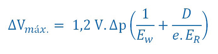
ΔVmax admissible loss (litres) V volume of the stretch to be tested (litres)
Δp admissible pressure drop during the test (20 kPa)
Ew bulk modulus of the water (2,1 x 10⁶ kPa)
Er modulus of ductility of the pipe´s material (kPa))
e nominal thickness of the pipe (m)
ID internal diameter of the pipe (m)
1,2: correction factor that takes into account, among other aspects, the effect of remaining air inside the pipe
If during the main test phase the pressure decreases or the loss water exceeds the acceptable values previously indicated, the detected faults must be corrected. This test will be repeat until it is successfully overcome.
